
Noodles: A Path Tracer Made of Blender Nodes
1 April 2023
What?
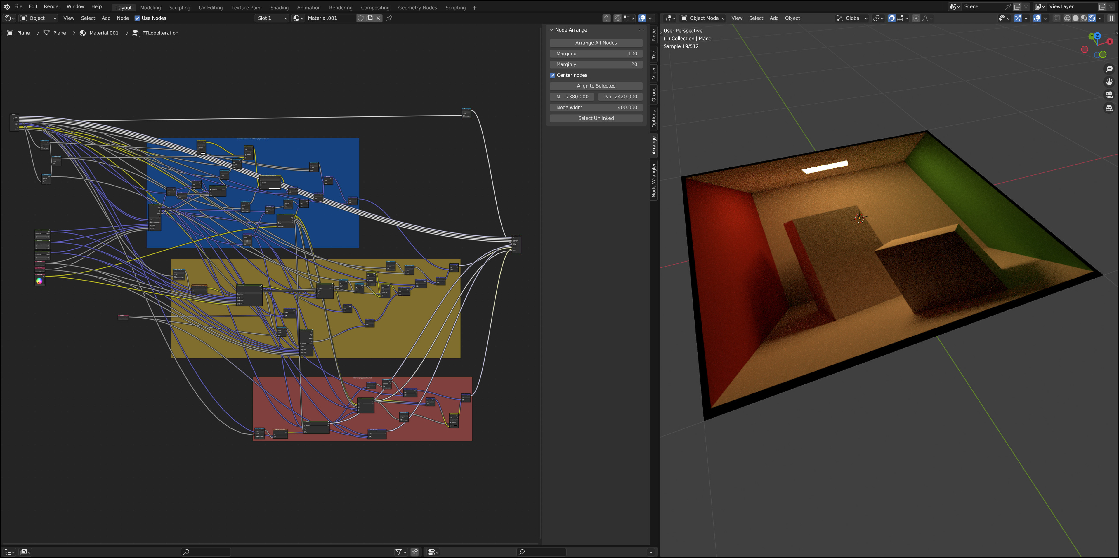
Noodles is a small physically based ray tracer implemented fully inside Blender's rendering engine. Specifically, it is implemented purely as a network of (many!) nodes assembled in the shader editor, see the illustration above.
Many rendering systems, including Blender, allow users to create and edit their own materials based on powerful node-based shader editors. For instance by combining multiple BRDFs using various "add" and "blend" nodes, or by creating procedural textures out of mathematical functions. As shown in this project, they are indeed flexible enough to implement a full raytracer inside a custom material.
Some basic "rules" apply: all nodes available in Blender's shader editor are fair to use, except for the Script Node which allows you to write arbitrary OSL code inside of it. This would defeat the main point of this project and take all the fun out of it. For similar reasons, no add-ons or custom Python scripting should be abused to generalize or circumvent the node system.
Noodles implements the following features:
-
The main rendering loop uses path tracing (including multiple importance sampling between BRDF and light sampling) to compute global illumination.
-
The virtual camera is based on the thin lens approximation and thus supports depth of field effects.
-
The scene can be built out of quad and sphere primitives, for which the relevant ray intersection functions are implemented. Both shapes can also act as area lights that cast soft shadows.
-
There is a diffuse + specular BRDF for simulating basic materials. In particular, a Fresnel-based mix of a Lambert BRDF and a specular microfacet model using the Trowbridge-Reitz (a.k.a. GGX) normal distribution function.
In principle, more features (e.g. more geometric primitives and materials) could be added—though there are some noteworthy limitations inherent to working with nodes:
-
Node graphs don't allow cycles,1 so there is no way to "jump back" and "execute" the same set of nodes multiple times. In other words, we can't actually implement loops in our program. The main consequence in the context of a simple path tracer is that we need to hardcode how many bounces of light we simulate.
-
It's unclear how to write a general system that can render arbitrary scenes. The scene geometry, materials, light sources, and the camera are therefore directly encoded inside the node graph.2
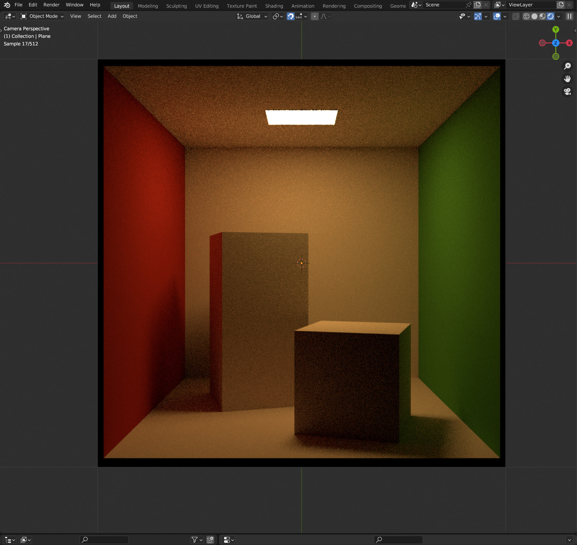
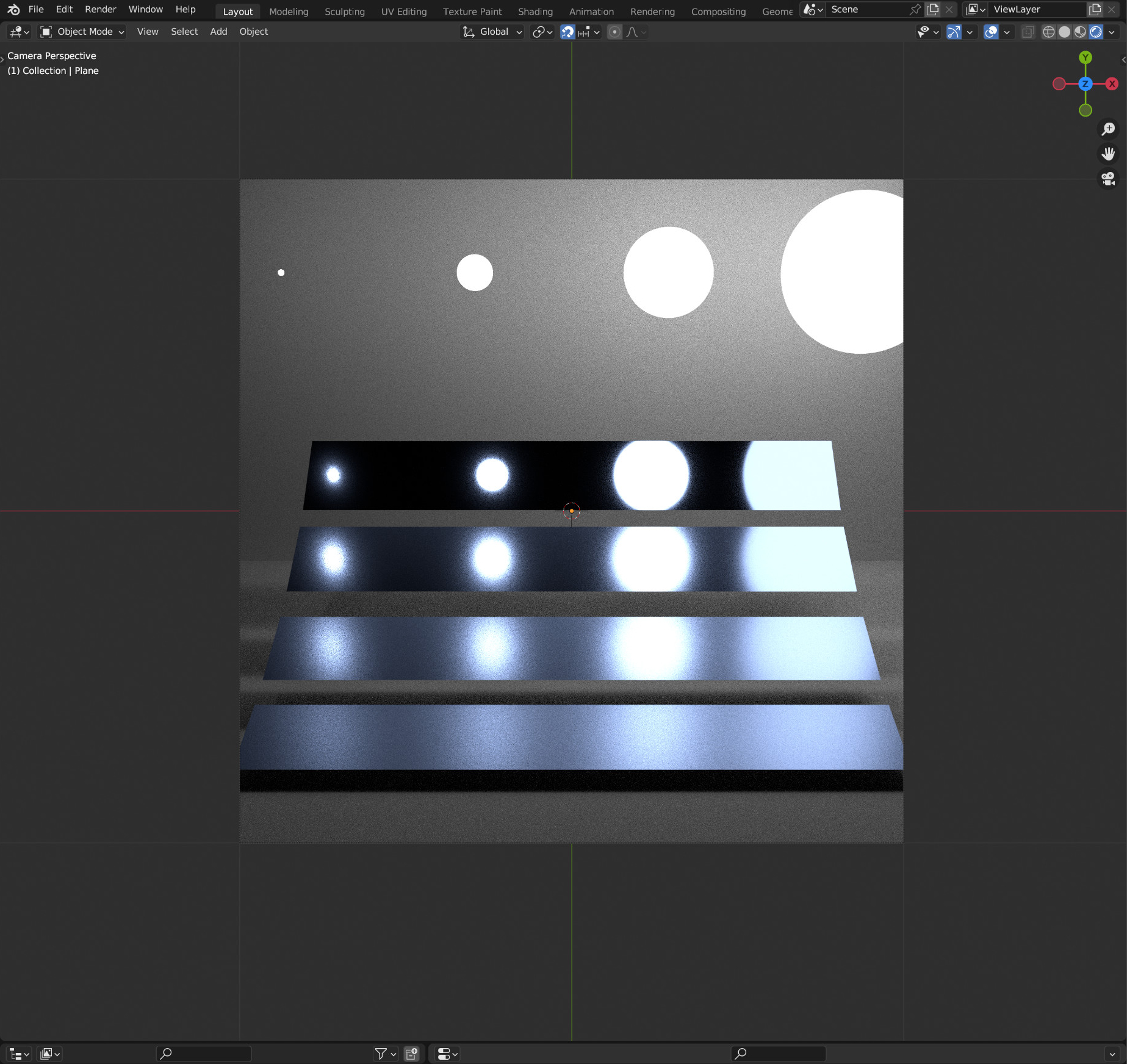
Here are two different test scenes that illustrate most of the available features. The associated Blender project files can be downloaded below, in case you want to play around with them yourself for some twisted reason.
A neat side effect of the node-based programming is that everything is procedurally generated and fully interactive. As shown in the following two animations, this means you can also edit scene parameters (as long as you can find the place inside the large graphs):
How?
A full summary of how this works would be unbearably long and likely even more useless than the renderer itself. Instead, this section briefly discusses the most important building blocks.
A procedural texture
Ultimately, the renderer is nothing else than a procedural texture that is applied to a quad in the scene. The very first step is therefore to extract the texture coordinates (UVs) of the quad, visualized with red and green gradients below. The Texture Coordinate Node does exactly this.
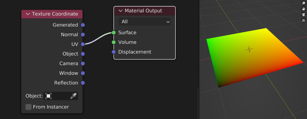
The node graph is responsible for computing the right color at each point on that texture. So each time the texture is evaluated, e.g. whenever a ray inside Blender's renderer hits the quad, the node graph runs our "nested" renderer.
Math nodes
A large part of writing a path tracer just involves evaluating mathematical equations. This is great because Blender has a Math Node that can directly evaluate all basic scalar math you need, including trigonometric functions:
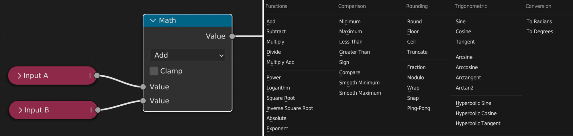
Conveniently, this also includes functions like Greater Than that are useful as boolean conditions during control flow (see the next paragraph). Note that the common logical operations And and Or can be implemented using Multiply and Add.
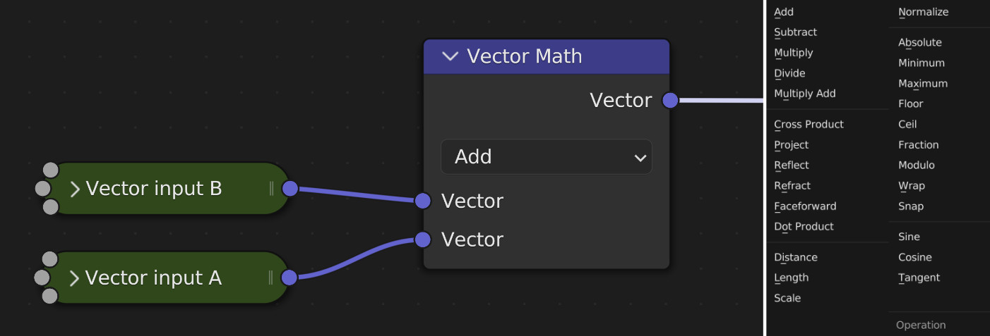
With the Vector Math Node we can also directly perform arithmetic on 3D vectors, including operations like dot products and norms. This makes it surprisingly easy to build most ray tracing functionality:
Control flow
This is where things become a bit more tricky. There is no explicit concept of conditional if/else statements in the node system and we need to resort to a rather cumbersome workaround. We will always execute both branches concurrently, and afterwards mask out one of the values based on a conditional. This is done by the Mix Node:
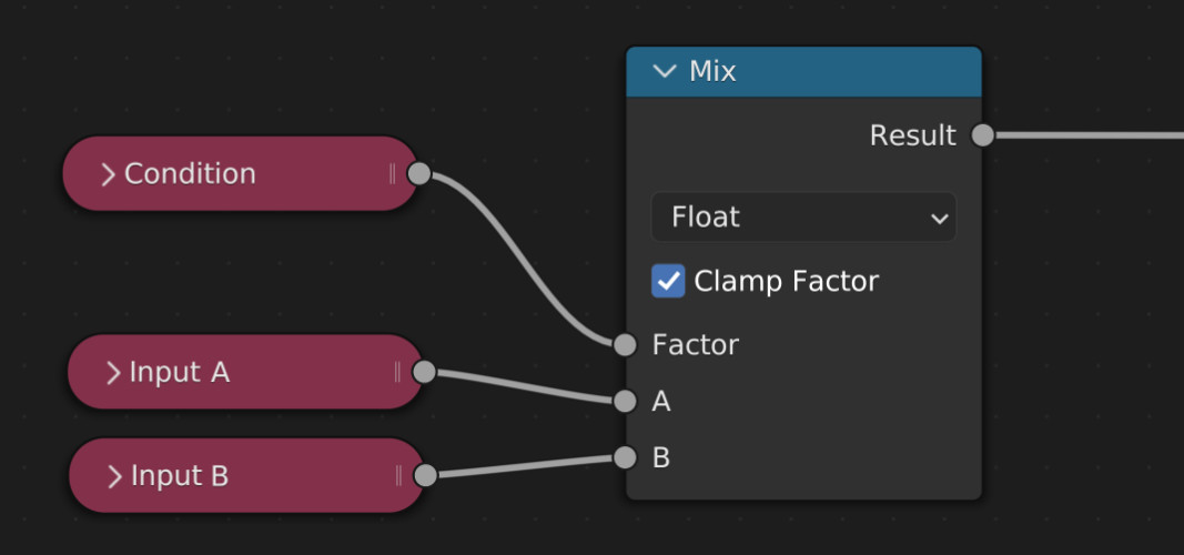
Based on the value of Condition, the Result here will either take on the value of A (in case of Condition == 0.0) or B (in case of Condition == 1.0). Some manual care is required to ensure Condition doesn't have any intermediate values as this would result in a linear blend of A and B which is usually meaningless in this context.
Node groups
The sheer amount of nodes necessary to translate all necessary code of a renderer quickly becomes unmanageable. A super useful feature in Blender to (somewhat) avoid this are Node Groups where arbitrary graphs can be succinctly re-used as a single "meta node" with its own inputs and outputs.
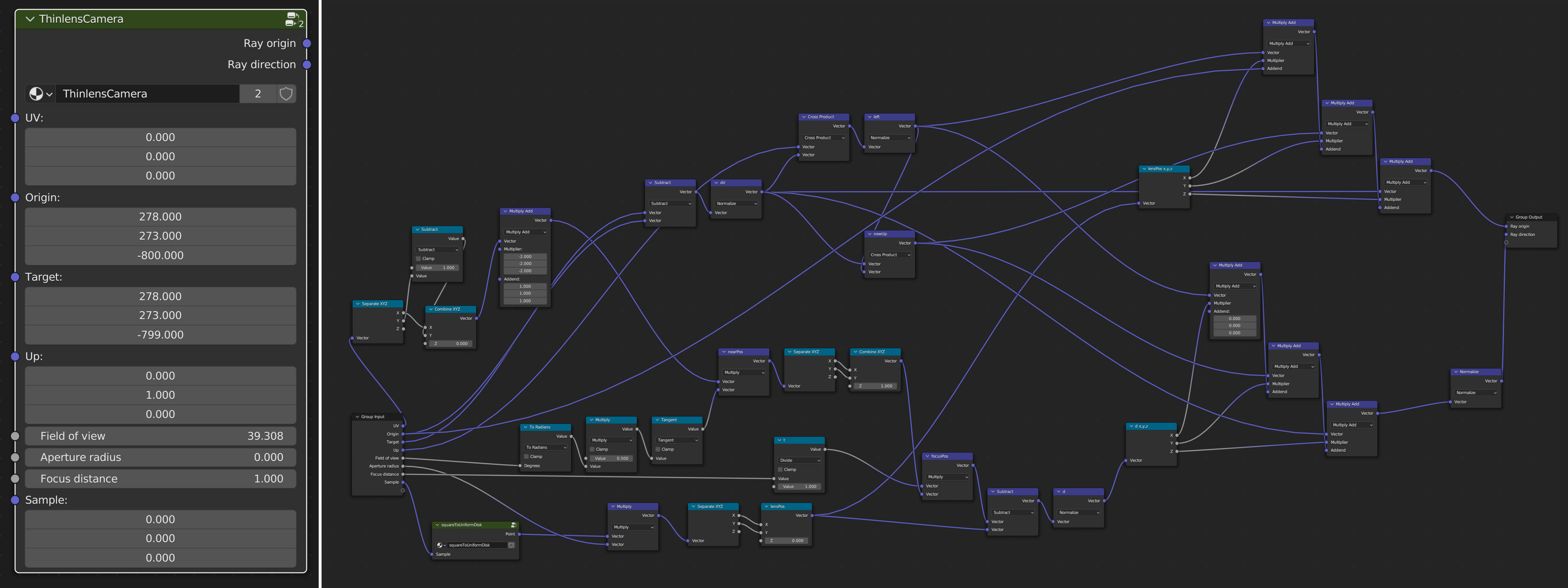
For instance, the following ThinlensCamera group abstracts away all details of the node graph shown on the right, responsible for generating rays from the camera given random numbers, some camera-specific parameters, and the UV coordinate of the original quad in Blender.
These can also be nested inside each other. This group, e.g., also includes another custom group called squareToUniformDisk which generates a uniformly random point on a 2D disk (used for offsetting the ray origin whenever the camera aperture size is nonzero).
Random numbers
Luckily there is no need to implement a hand-written (pseudo) random number generator via nodes. We can directly hijack Blender's White Noise Texture Node that will output the required random numbers for performing Monte Carlo integration in the path tracer:
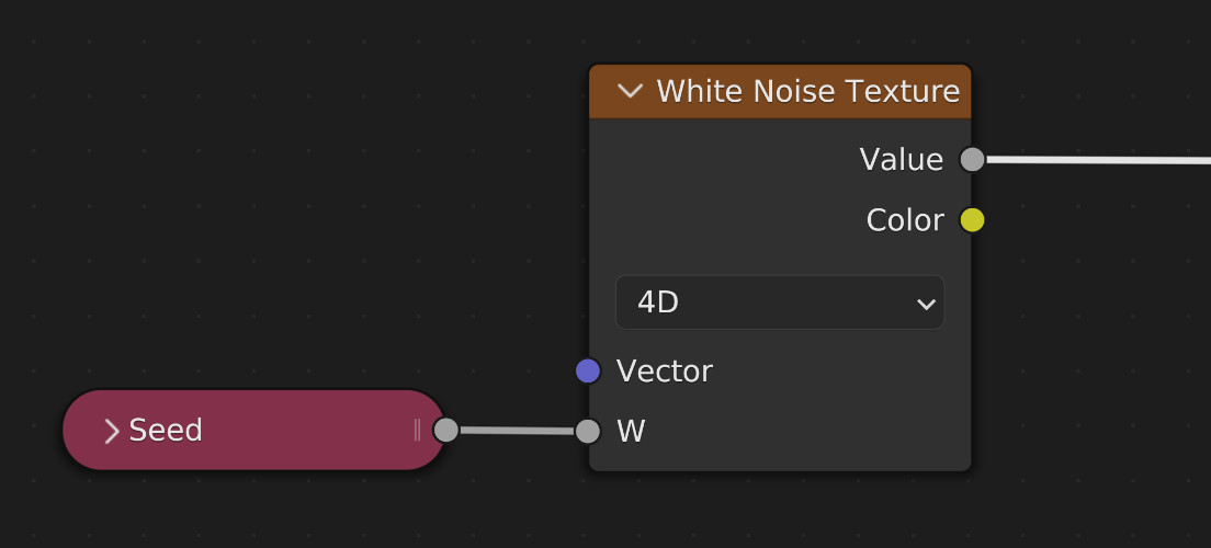
An important detail is to use different seeds each time a random number is generated in the graph, e.g. whenever a new ray direction is sampled after scattering on a surface. Otherwise, the final rendering will be contaminated by correlation artifacts.
Textures
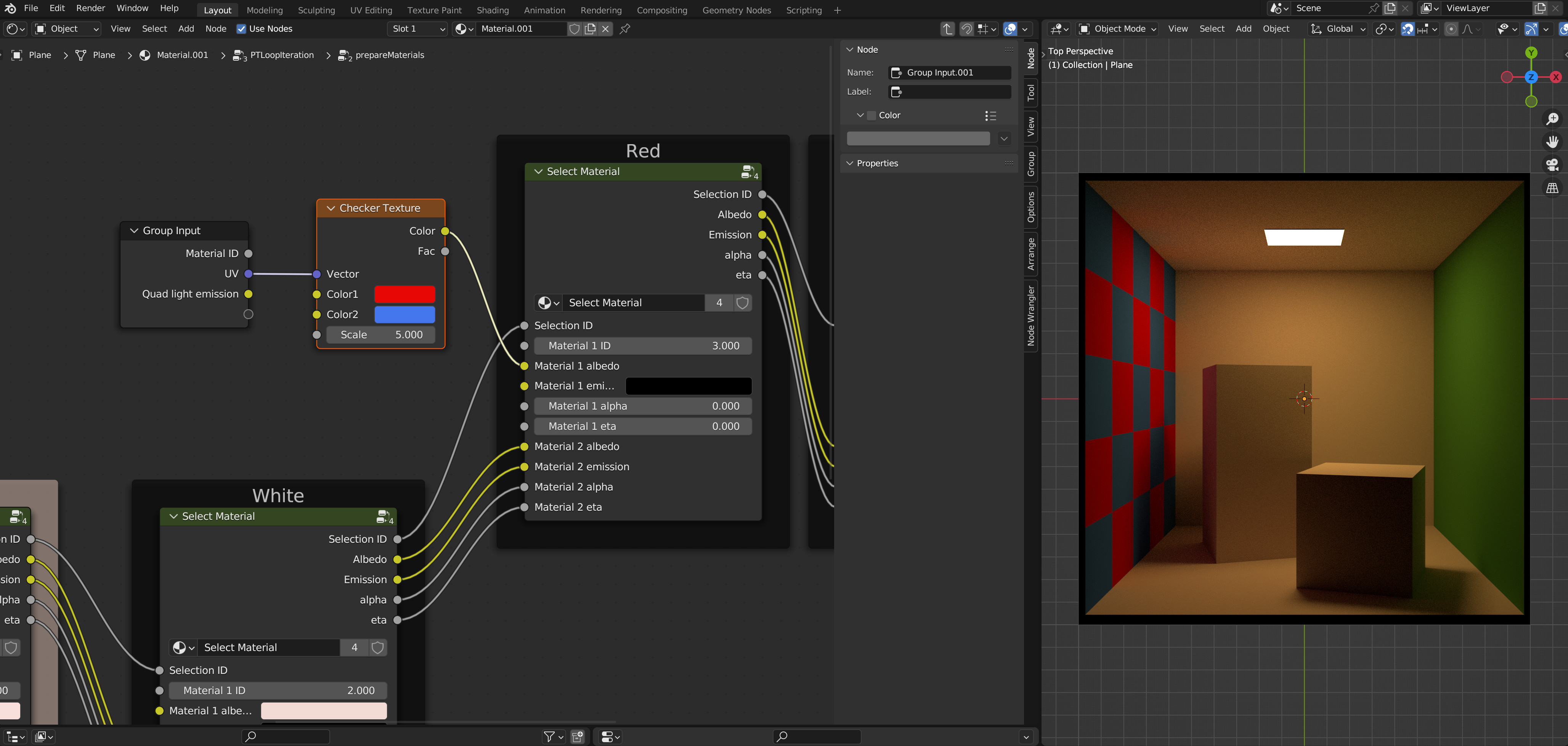
While the two demo scenes above don't use any textures, this is another feature that can easily be added by just hijacking Blender's existing node infrastructure. This time by using any of the various Texture Nodes.
All that is needed is to compute suitable UV coordinates of the intersected geometric primitives (quads and spheres) and plugging them into the node. In this example, the red wall of the Cornell box was replaced by a procedural checkerboard texture:4
Ray intersections against the scene
Finding the closest intersection point in the scene along a given ray is the first time where loops could really be useful. The next image shows the full intersection routine against the Cornell box scene, built from 18 quads (one area light, five walls and twelve faces of the two boxes inside).
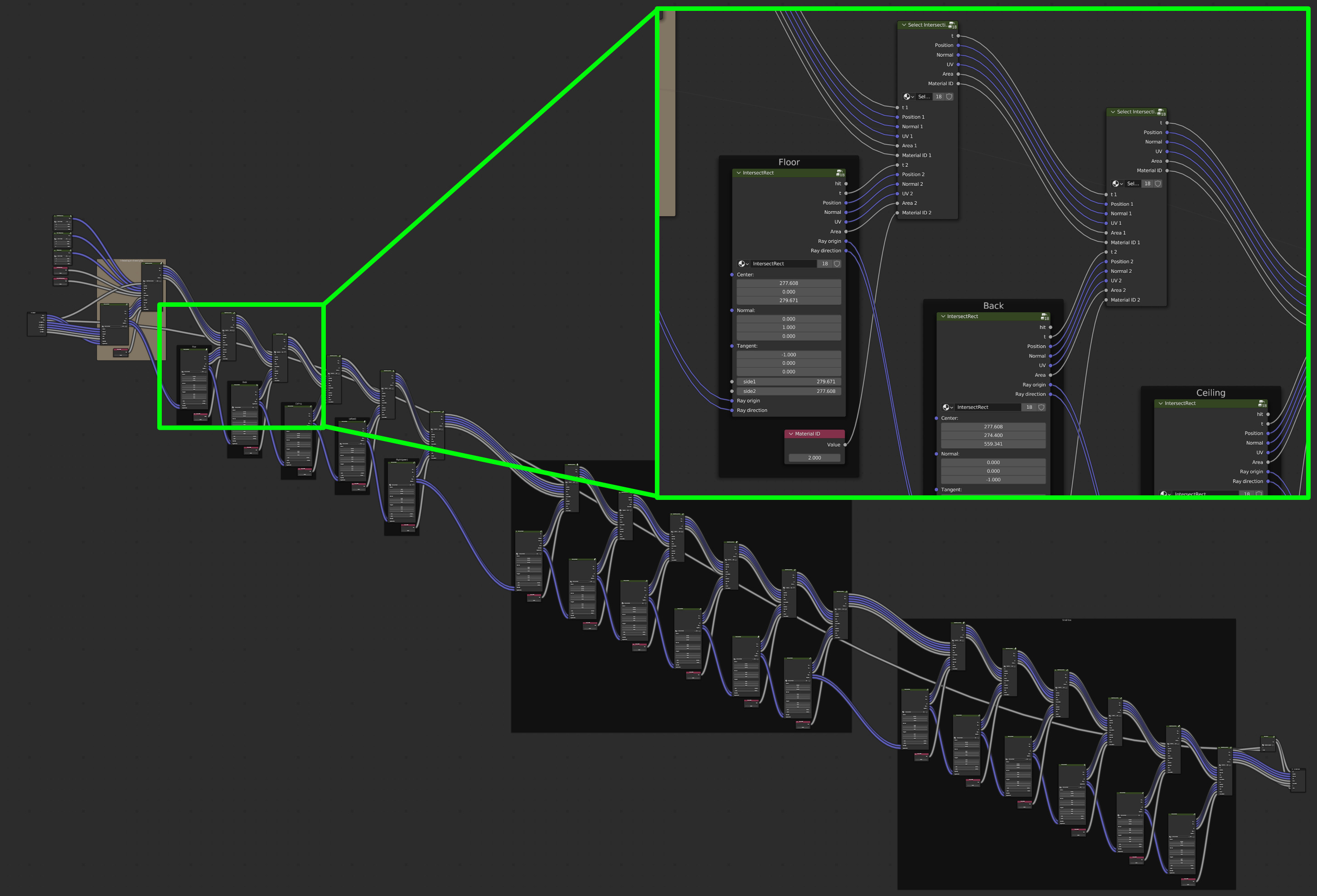
Intersecting each primitive involves one node group for the actual intersection (here IntersectRect), combined with a Select Intersection group that forwards all information about the closest found hit (so far) along the chain.
One path tracing iteration
A single iteration of the path tracer, i.e. one bounce of light, is shown in the next image.5
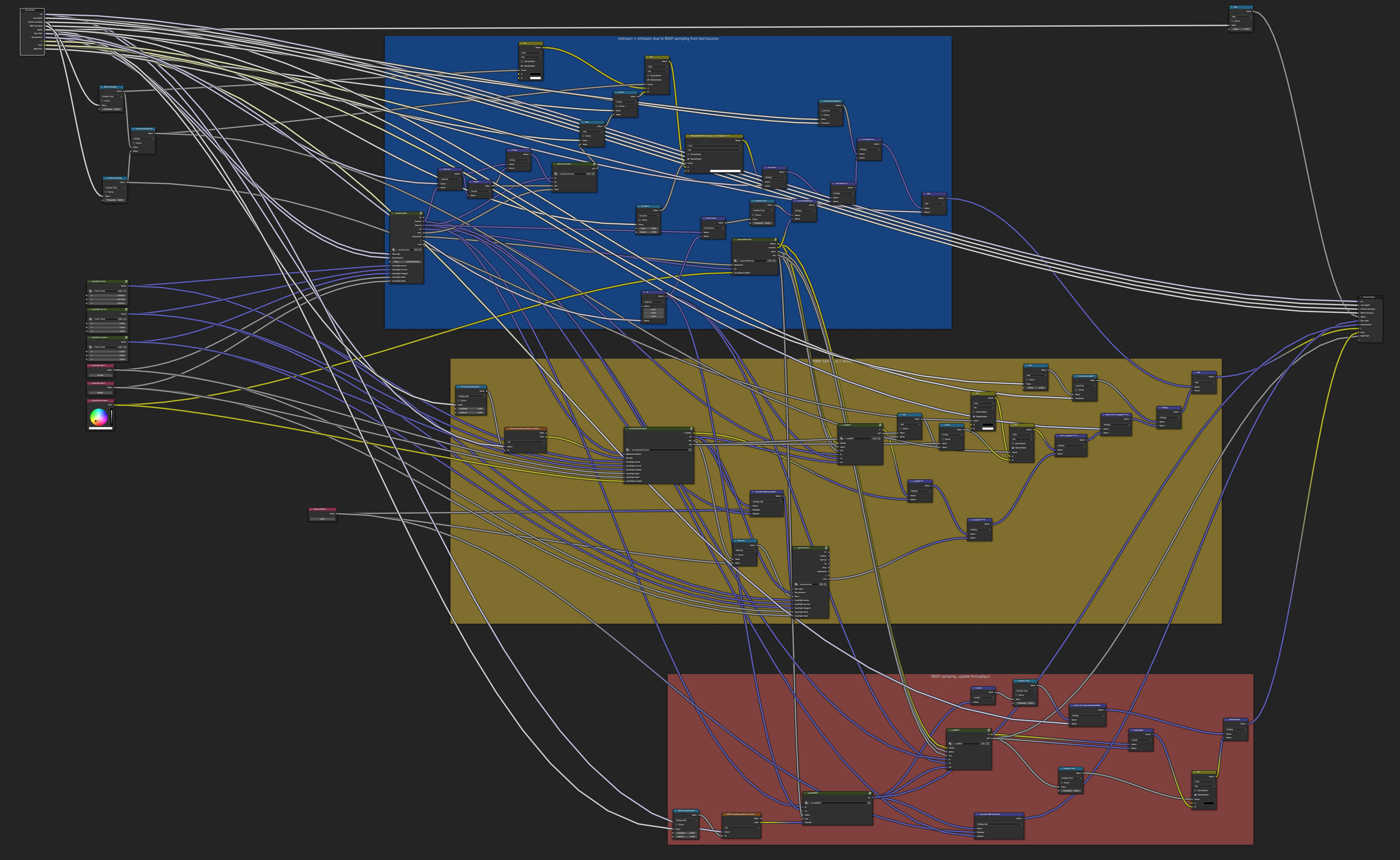
The colored boxes are a desperate attempt at keeping things organized:
-
The blue box is responsible for intersecting the scene and accounting for emission at the found position.
-
The yellow box contains nodes for sampling a position on a light source, tracing the corresponding shadow ray, and evaluating the BRDF.
-
The red box samples a new ray direction based on the BRDF properties at the current location.
The large sceneIntersect node group from above therefore appears twice in this larger graph. Many more node groups (that are glossed over completely in this summary) are abstracting away the specifics of light sources and BRDFs.
As a last step in this graph, the outputs of the first two boxes are combined via multiple importance sampling, with weights based on the probabilities of the respective sampling techniques.
The outer-most loop
After nesting enough node groups inside each other, things start to become more manageable again at this point. Because we can't use actual loops, we now copy the node group of one iteration a fixed number of times to account for multiple bounces of light. Each node takes in the full "state" of the current light path, modifies it internally, and returns the new version. At the very end we output the radiance along the ray as the final color values.
And voilà!

Why?
While I like building renderers I can't think of any (good) reason that would justify this whole project. It's interesting to push Blender to its limits—but in the end this is mostly a silly joke idea that was taken way too far.
This is also a good place to thank Baptiste Nicolet for encouraging me to actually do this and helping with prototyping and solving some of the conceptual challenges.
Downloads
Both of these .blend files are tested with Blender version 3.5.
Footnotes
- This is of course quite ironic, given that Blender's main rendering engine is called Cycles. ↩
- It would be quite spectacular if you could somehow render the actual scene opened in Blender. Please let me know if you can think of a way to achieve this!↩
- E. Veach and L. J. Guibas. 1995. Optimally Combining Sampling Techniques for Monte Carlo Rendering. In Proceedings of the 22nd annual conference on Computer graphics and interactive techniques (SIGGRAPH '95). ↩
- As the renderer itself is essentially evaluating a procedural texture we could also plug in a recursive evaluation of the whole node graph at this point. This is left as an exercise to the reader :) ↩
- It also serves as inspiration for the name of the renderer. ↩