Intermediate Features
Layered BSDFs
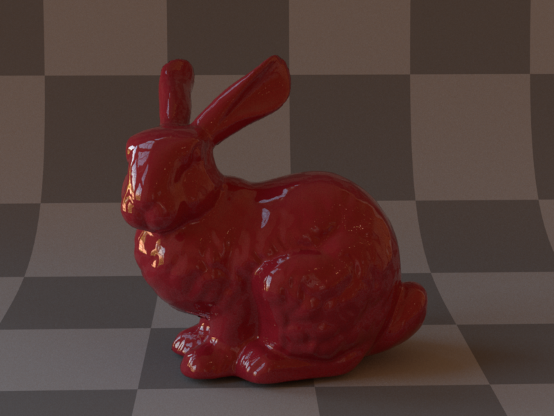
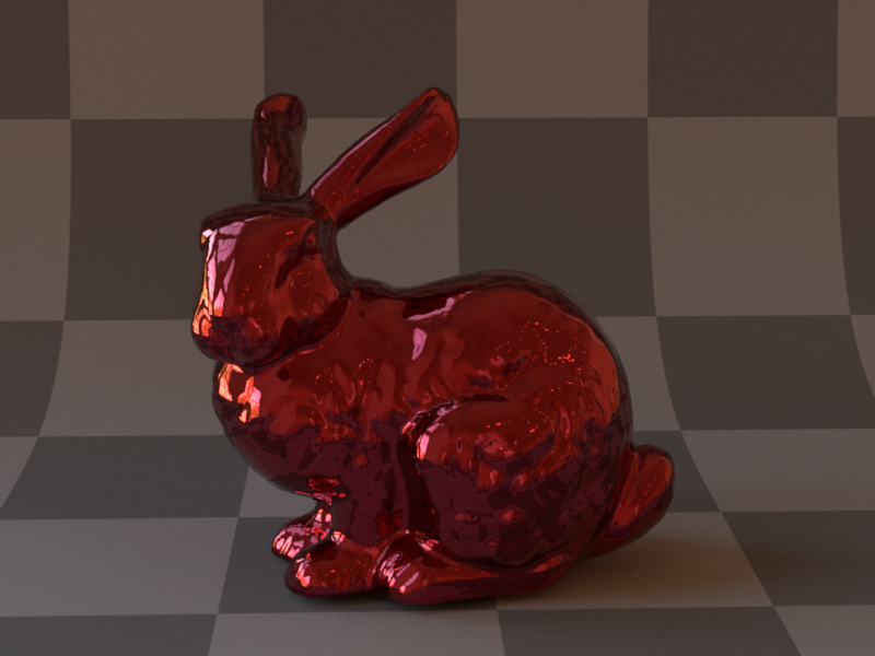
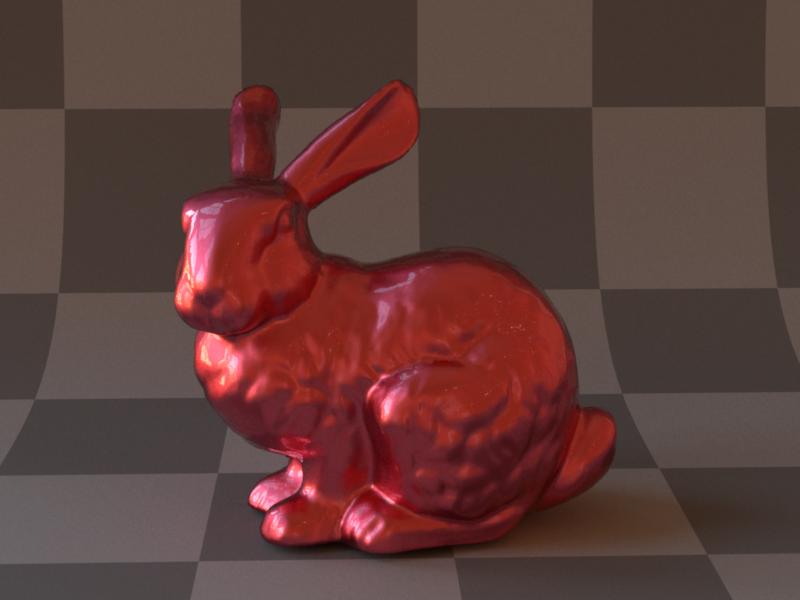
Layered BSDFs can have very interesting appearances. For the crayons in my final scene, I had to implement some sort of smooth varnish. The result is a Smooth Dielectric Coating BSDF in the style of Arbitrarily Layered Micro-Facet Surfaces by Weidlich and Wilkie. The coating can be applied to any sort of base layer BSDF, which can produce a variety of results.
Because of many simplifying assumptions made in the paper, the presented BSDF models are not entirely physically accurate, but still produce visually appealing results which I tried to reproduce as closely as possible.
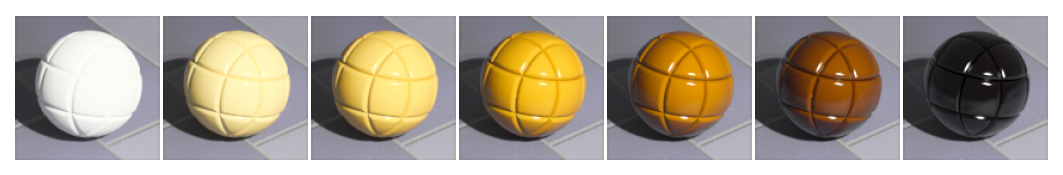
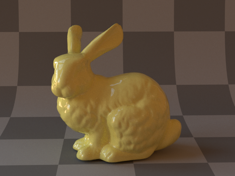
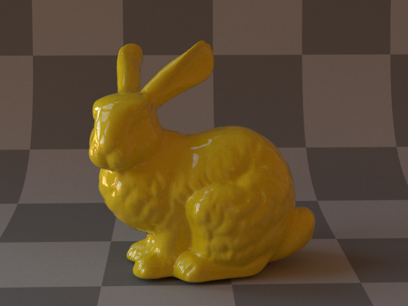
See below for comparisons with figures from the paper. The first set of images illustrates some of the combined BSDF types that can be created with the coating. The second set shows the effect of an increasing thickness parameter of an absorbing, tinted varnish.
Code:
src/bsdfs/coating.cpp
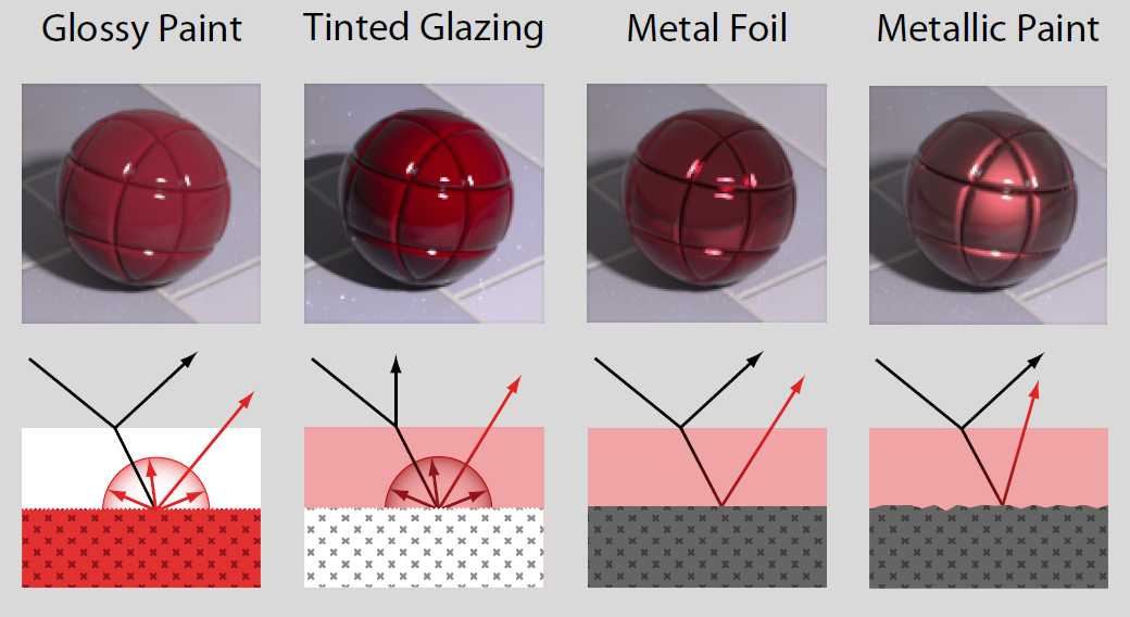
(Image from Arbitrarily Layered Micro-Facet Surfaces by Weidlich and Wilkie.)

(Image from Arbitrarily Layered Micro-Facet Surfaces by Weidlich and Wilkie.)

Coating thickness 0.0001
Coating thickness 0.6
Coating thickness 2.0
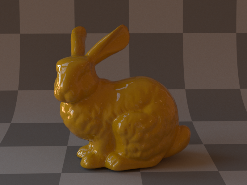
Coating thickness 5.0
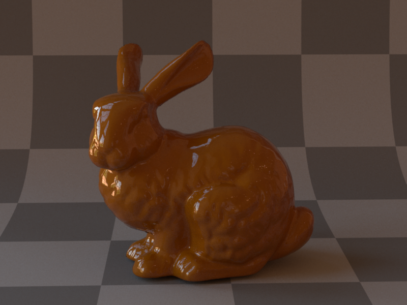
Coating thickness 10.0
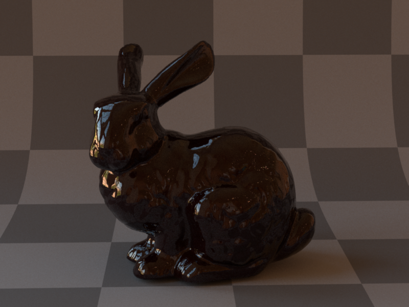
Coating thickness 40.0
Image Based Lighting
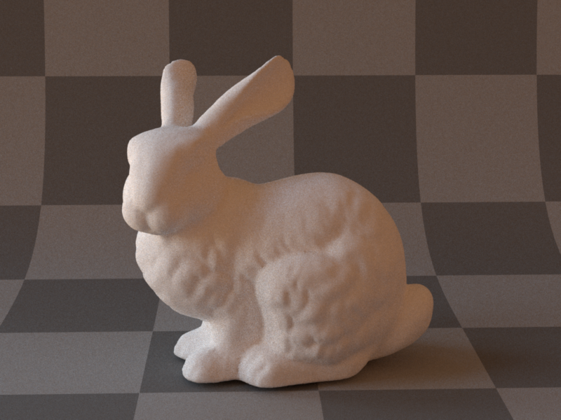
Image Based Lighting is a technique that can produce very natural and realistic looking illumination of a scene using an environment map.
I implemented a version with importance sampling, using the hierachrical sample warping strategy discussed in the lecture.
See below for an image of a diffuse object rendered using Image Based Lighting. Note the varying colour and brightness along the surface.
Most test images in this report use this lighting technique as well.
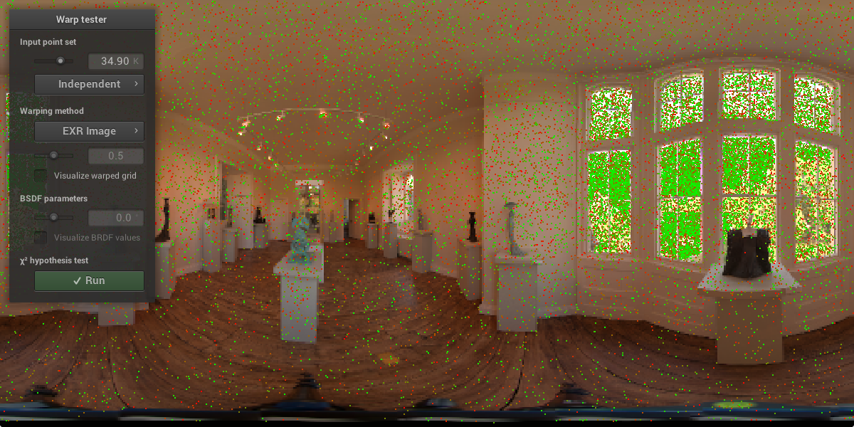
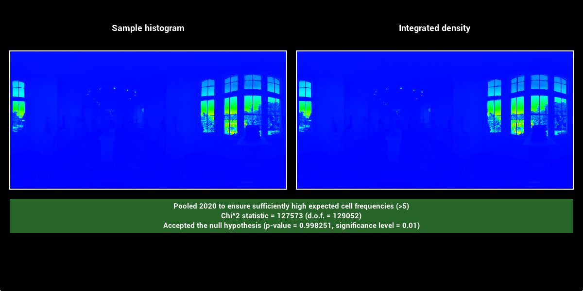
You can also find an example of possible sample placements for an environment map below, together with a chi^2 test that the samples are distributed correctly based on the probability density function defined by the luminance of the texture.
Code:
include/nori/lightprobe.hsrc/bsdfs/lightprobe.cppsrc/bsdfs/emitters/envmap.cpp

Volumetric Path Tracing
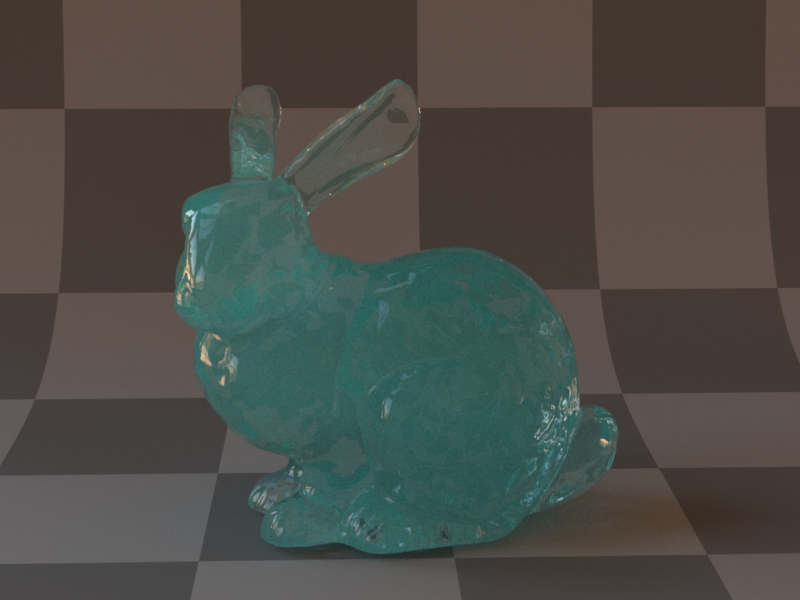
For the glass of coloured water in my scene, I had to implement some way to handle participating media in my renderer. I chose a simple version of Volumetric Path Tracing that is built with the requirements of my final image in mind: It handles only homogeneous media with an isotropic phase function.
The implementation is based on the "Basic Volumetric Path Tracer" psudocode from the lecture slides. It only supports material sampling, as my final image can't benefit from MIS because of the dielectric boundaries around the water.
Because every mesh in my renderer needs a BSDF attached to it, I created a special Transmittance BSDF which effectively does nothing on a ray intersection to use with meshes that act only as virtual boundaries around volumes.
See below for various results with different absorption and scattering coefficients together with their respective Mitsuba references.
Code:
include/nori/medium.hinclude/nori/phase.hsrc/mediums/homogeneous.cppsrc/phases/isotropic.cppsrc/bsdf/trans.cpp
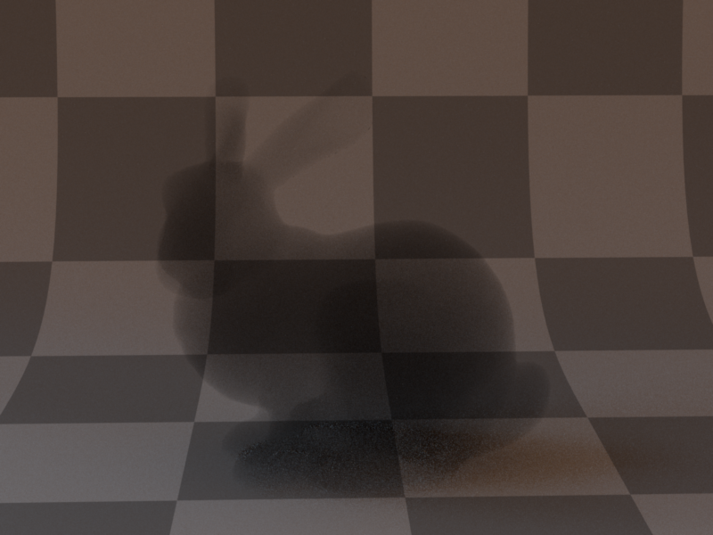
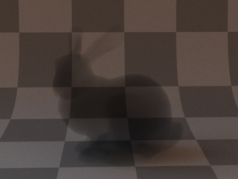

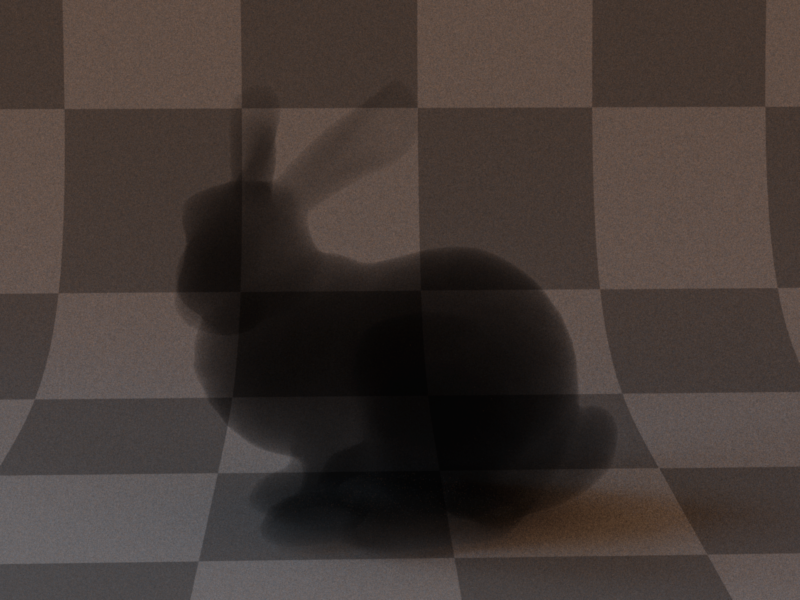
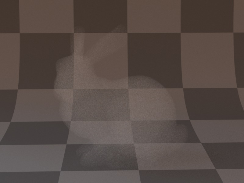

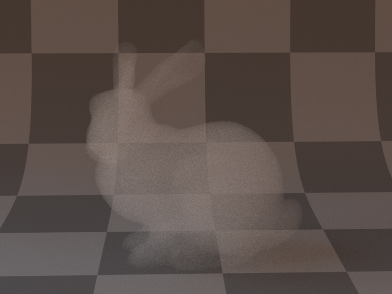
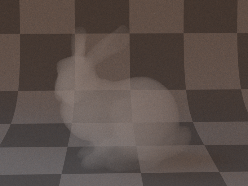
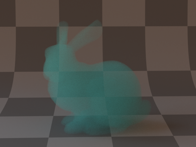
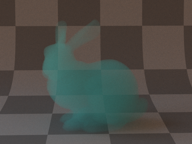
sigmaA = [0.8, 0.2, 0.2], sigmaS = [0.2, 0.8, 0.8]